A laboratory measurement of a noise control device answers one question: what is this product worth, under conditions chosen so that two products can be compared. It is the right question when there is a catalogue to write. It is the wrong one when the silencer is already welded into the duct, the screen has been standing between the press and the bench for a year, and the barrier was built before anyone thought of measuring it.
These three standards ask the other question. Each of them measures a device where it already stands, in the installation it belongs to, with whatever is around it.
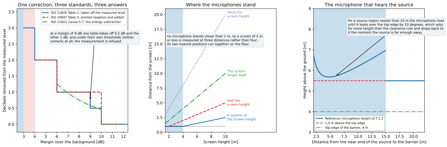
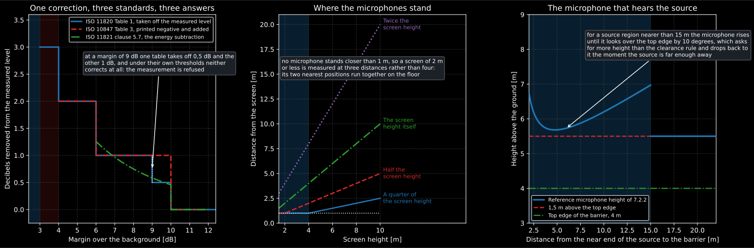
Three standards, three answers to the same question about background noise; the microphone positions a screen measurement uses; and the one microphone whose whole job is to hear the source rather than the device.
1. What in situ costs, and what it buys
Section titled “1. What in situ costs, and what it buys”The laboratory buys two things: a controlled environment, and a substitution measurement. ISO 7235 measures a duct silencer by running a source into a test duct with the silencer in place, then with a straight replacement section of the same length, so that the two runs differ by the silencer alone.
In situ neither is available. The environment is whatever room, duct or open space the device sits in, and there is no replacement section to swap in. What is left is the pair of levels the installation allows, and the arithmetic that turns them into a quantity: the ratio of the two measurement areas, and the difference of the two field corrections.
That is Equation (19) of ISO 11820, and it is the whole idea of measuring in situ. The level difference is what a meter reads. The area term converts each side’s mean level into the sound power it stands for, because the source side may be a duct cross-section while the receiver side is a room. The field corrections carry whatever the two sides do not share.
from phonometry import noise_control
bands = [125.0, 250.0, 500.0, 1000.0, 2000.0, 4000.0]source = [98.0, 99.0, 97.0, 95.0, 92.0, 88.0]     # dB, in the ductreceiver = [72.0, 68.0, 60.0, 54.0, 50.0, 49.0]   # dB, in the room it feeds
res = noise_control.in_situ_transmission_loss(    source, receiver,    source_area_m2=0.9,      # the duct cross-section    receiver_area_m2=10.8,   # a quarter of the room absorption at 500 Hz    frequencies=bands, case=2,)print(res.loss_db.round(1))        # [15.2 20.2 26.2 30.2 31.2 28.2] dBprint(res.area_term_db.round(1))   # [-10.8 -10.8 -10.8 -10.8 -10.8 -10.8] dB
The area term is negative here and that is not a mistake. A duct of 0,9 m² discharging into a room whose quarter-absorption is 10,8 m² spreads the same power over twelve times the area, so the room is already quieter than the duct before the silencer does anything. Subtracting that is what stops the room being credited to the silencer. The term comes back once per band even here, where both areas were typed as single numbers, because the area of a room is not one number: the next section shows why.
2. The twenty installations
Section titled “2. The twenty installations”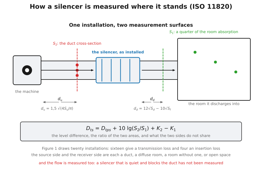
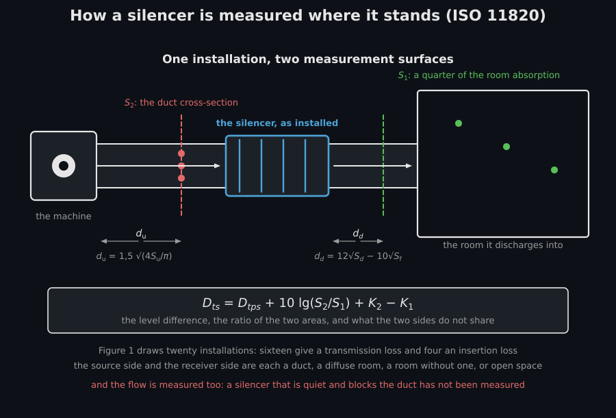
A silencer sits between two of four things: a duct, a room with a diffuse field, a room without one, and open space. Sixteen pairs of those are transmission measurements and four more are insertion measurements, and Figure 1 draws all twenty. The area rule for each side follows from what that side is, and clause 9 states it.
case = noise_control.installation_case(2)print(case.source_side, case.receiver_side) # duct diffuse_roomprint(case.quantity) # transmissionprint(case.receiver_area_rule)# one-quarter of the absorption of the receiver roomNaming the case is not decoration. in_situ_transmission_loss refuses a case
that belongs to the insertion set and in_situ_insertion_loss refuses the
opposite, because Equations (19) and (21) are two quantities and Figure 1 is
what says which one an installation can give.
The room area itself comes from the reverberation time, through Equations (6), (10) and (12), which are the same expression written three times:
area = noise_control.reverberant_surface_area_m2( 320.0, [1.6, 1.4, 1.2, 1.1, 1.0, 0.9],)print(area.round(1)) # [ 8.1 9.3 10.8 11.8 13. 14.4] m^2It is a quarter of the Sabine equivalent absorption area, which is the factor that turns a reverberant level into a sound power. A reverberation time is a band quantity, so the area is one too, and the 10,8 m² of section 1 was only its value at 500 Hz. Both loss functions take each area, and the field correction, as one value for every band or as one value per band, so the array goes in as it comes out:
res = noise_control.in_situ_transmission_loss( source, receiver, source_area_m2=0.9, receiver_area_m2=area, frequencies=bands, case=2,)print(res.area_term_db.round(1)) # [ -9.6 -10.1 -10.8 -11.2 -11.6 -12.1] dBprint(res.loss_db.round(1)) # [16.4 20.9 26.2 29.8 30.4 26.9] dBAt 500 Hz nothing moves. Below it the room is more reverberant, its area smaller and the silencer credited with more, by 1,2 dB at 125 Hz; above it the other way round, by 1,3 dB at 4 kHz. The duct cross-section stays one number, because it is one.
3. The silencer that is quiet and blocks the duct
Section titled “3. The silencer that is quiet and blocks the duct”A silencer has not been measured until the flow has been measured too. ISO 11820 devotes clause 9 to it, and the library carries the whole chain: the total pressure loss of Equation (13), the static difference behind a change of area of Equation (14), the velocity pressure and the velocity it stands for, the gas density of Equation (29), and the velocity inside the silencer of Equation (31), which is the one the regenerated noise answers to.
print(round(noise_control.gas_density_kg_m3(temperature_c=120.0), 3)) # 0.887print(round(noise_control.silencer_flow_velocity_m_s( 8.0, upstream_area_m2=0.9, free_area_m2=0.45), 1)) # 16.0The measurement surfaces have their own geometry. Upstream, one and a half equivalent diameters of the measurement cross-section; downstream, , which for a silencer whose free area is most of the duct can fall to zero or below. The standard has its own escape for that, which is agreement between the parties, and the case is reported rather than returned as a distance nobody can stand at.
How the measurement goes
Section titled “How the measurement goes”Choose the installation from Figure 1 and read off which area rule each side takes. Place the source-side surface one and a half equivalent diameters upstream of the silencer and the receiver-side surface at the distance Equation (16) gives, or agree on one when that expression falls to zero. Run the machine, measure the mean level on each surface, and measure the extraneous sound with the switchable sources off if you can, because the energy route of Equations (17) and (18) is better than the stepped table and both refuse under 3 dB anyway. Record the temperature on both sides: where they differ, the field correction of Equations (20) and (22) is not zero. Then measure the flow, the total pressure loss across the silencer and the velocity profile in the duct, which 9.2 asks to be uniform within 10 %.
4. The screen you can take away
Section titled “4. The screen you can take away”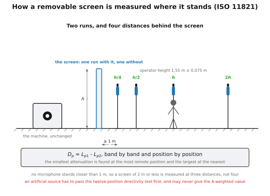
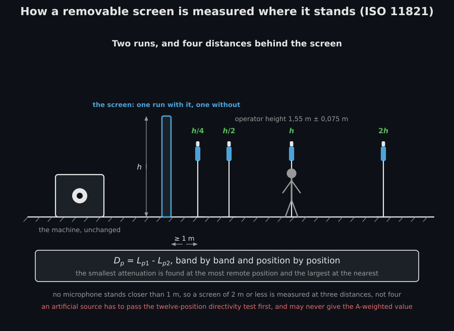
ISO 11821 has the one thing the other two lack: the device can be removed for a run. A removable screen is wheeled aside, the room is measured, the screen is wheeled back, and the difference is the attenuation.
res = noise_control.screen_attenuation( [78.0, 80.0, 81.0, 79.0, 76.0, 72.0], # dB, screen away [74.0, 74.0, 72.0, 68.0, 63.0, 58.0], # dB, screen in place frequencies=bands, a_weighted_unscreened_level_db=84.1, a_weighted_screened_level_db=74.6,)print(res.attenuation_db) # [ 4. 6. 9. 11. 13. 14.] dBprint(res.a_weighted_attenuation_db) # 9.5 dBprint(res.rounded()) # [ 4 6 9 11 13 14] dBprint(res.rounded_a_weighted()) # 10 dB7.4 c) reports both to the nearest whole decibel. rounded() and
rounded_a_weighted() give them that way, as integers, while attenuation_db
keeps the unrounded difference to compute with. An exact half goes to the even
decibel, as in the other in-situ results of the library, so the 9,5 dB above is
reported as 10 dB.
The A-weighted pair is clause 5.9, and it comes with a condition the library
enforces rather than mentions: it may not be obtained with an artificial source.
An A-weighted number weights a spectrum, and with a loudspeaker standing in for
the machine the spectrum weighted is the loudspeaker’s. Asking for one anyway
raises ValueError rather than returning a number that would be reported as the
machine’s.
An artificial source has a test of its own to pass first. Definition 3.10 reads the directivity index at twelve positions evenly spaced on a horizontal circle of about 1,5 m radius, as the logarithmic mean less the position, and 5.2.2 accepts the source while no position falls more than 8 dB below the mean.
Where the microphones stand is 5.5.2: a quarter, a half, once and twice the screen height, never closer than 1 m. Under 4 m the quarter-height position falls inside that floor and is pushed out to it, and at 2 m and under the half-height one is pushed out too, so the two nearest positions coincide and the measurement is made at three distances. That is the printed rule rather than an oversight.
print(noise_control.microphone_distances_m(3.0)) # [1. 1.5 3. 6. ] mNOTE 2 says what the spread of those four answers means: the smallest attenuation is found at the most remote position and the largest at the nearest, which is why the standard asks for all four rather than for an average.
How the measurement goes
Section titled “How the measurement goes”Put the microphones on the line perpendicular to the screen, at a quarter, a half, once and twice its height, and push the ones that fall inside 1 m out to 1 m. Set each of them at the operator height where the workplace does not fix one. Run the machine with the screen in place, take the levels, wheel the screen away without touching anything else, and take them again. Measure the background with the machine off at the same positions: over 10 dB of margin needs no correction, between 6 dB and 10 dB takes the boxed formula of 5.7, and under 6 dB the conditions are not acceptable and the answer is to come back on a quieter day. For an impulsive source, at least three repeats with the S time weighting, and the arithmetic mean of them.
5. The barrier that was built years ago
Section titled “5. The barrier that was built years ago”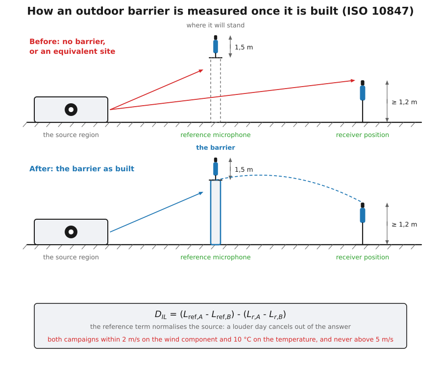
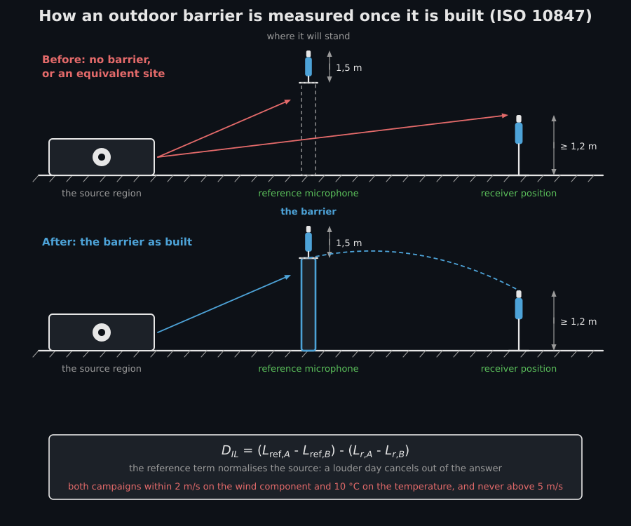
An outdoor barrier cannot be removed and usually cannot be measured before it exists. ISO 10847 offers two ways out, and is honest about what each is worth.
The direct method needs the site before the barrier was built. Both campaigns use the same receiver positions and the same reference microphone, and the reference term normalises the source: whatever ran differently on the second day, the reference microphone heard it too.
from phonometry import environment
res = environment.measured_insertion_loss_direct(    [76.0, 74.0, 71.0, 67.0, 62.0, 56.0],   # reference, before    [78.0, 76.0, 73.0, 69.0, 64.0, 58.0],   # reference, after    [63.0, 61.0, 58.0, 54.0, 49.0, 43.0],   # receiver, before    [58.0, 53.0, 47.0, 41.0, 35.0, 29.0],   # receiver, after    frequencies=bands,)print(res.insertion_loss_db)   # [ 7. 10. 13. 15. 16. 16.] dB
The source was 2 dB louder on the second day in every band, and the answer does not contain those 2 dB. That invariance is the reason the reference microphone exists.
The indirect method borrows the “before” campaign from a substitute site judged equivalent in terrain, ground and source, which makes it an estimate and the standard says so. Each campaign carries a correction for the kind of receiver position, 0 dB in a hemi free field and 6 dB against a facade where the pressure doubles.
The reference microphone stands at least 1,5 m above the top edge of the barrier, measured from its highest point where the top is not a straight edge, and 7.2.2 says so with “shall”. Where the near end of the source region is closer than 15 m, the NOTE to 7.2.2 lets the microphone be raised further, until it looks over the top edge by 10 degrees. The NOTE only ever raises it, so the height is the higher of the two. A 4 m barrier 8 m from the source takes the angle; a 3 m barrier 5 m from the source reaches its 10 degrees at 4,34 m and keeps the 4,5 m of the clearance:
print(round(environment.reference_microphone_height_m( 4.0, source_to_barrier_m=8.0), 2)) # 5.93 mprint(environment.reference_microphone_height_m( 3.0, source_to_barrier_m=5.0)) # 4.5 mprint(environment.reference_microphone_height_m(4.0)) # 5.5 mWhere the top of the barrier already stands 80 degrees or more above the near
end of the source region, no height reaches the 10 degrees at all. The
microphone then keeps the clearance, and a BarrierInSituWarning says the NOTE
could not be followed.
6. The weather is part of the measurement
Section titled “6. The weather is part of the measurement”Two campaigns separated by months are two different days of weather, and clause 6 spends most of its length on that. The wind enters as the vector component of the average velocity on the line from the source to the receiver, positive downwind. Table 1 gives a downwind class and a calm one over any distance, and adds an upwind class over short distances alone.
print(environment.wind_class(2.5)) # downwindprint(environment.wind_class(-2.0, short_distance=True)) # upwindprint(environment.wind_class(-2.0)) # NoneWhether the geometry is a short distance is not a matter of opinion either. 6.3.1 prints one inequality for the “before” campaign and two for the “after” one, all against the same ratio of 0,1, and the two campaigns can disagree:
print(environment.is_short_distance( source_height_m=1.0, receiver_height_m=1.5, barrier_height_m=4.0, source_to_barrier_m=10.0, barrier_to_receiver_m=20.0,)) # (False, True)Above 5 m/s in absolute value no measurement is made at all, which is a refusal rather than a class. The two campaigns must also agree within 2 m/s on the component and within 10 °C on the temperature, and the cloud cover is recorded in the four classes of Table 2, because the temperature gradient that bends a ray outdoors is not measured directly and the sky is the best proxy available.
How the measurement goes
Section titled “How the measurement goes”Fix the receiver positions and the reference position first, and keep them for both campaigns: the subtraction means nothing otherwise. Put the reference microphone at least 1,5 m above the top edge of the barrier, on a vertical plane through it, measured from the highest point where the top is not a straight edge, and higher where the source region comes closer than 15 m and the elevation rule of the NOTE asks for more. Record the wind component on the source-to-receiver line, the temperature and the cloud cover for every run, and stop when the wind passes 5 m/s. Repeat at least three times. When the second campaign comes, check that the weather still matches within 2 m/s and 10 °C before anything else, because nothing downstream can repair a mismatch there.
7. One correction, three standards, three answers
Section titled “7. One correction, three standards, three answers”All three documents face the same problem: the measured level contains sound that did not come from the source. All three answer it differently, and the differences are not rounding.
ISO 11820 prints a stepped table, positive, to be subtracted: 3 dB at a margin of 3 dB, falling to 0,5 dB at 9 and 10, nothing above, and under 3 dB the measurements are invalid. ISO 10847 prints a stepped table, negative, to be added: 2 dB at a margin of 4 or 5, 1 dB from 6 to 9, nothing from 10 up, and under 4 dB the results are not valid. ISO 11821 prints no table at all and boxes the energy subtraction, correcting only inside a window from 6 dB to 10 dB and refusing anything narrower, because the background it names includes wind-generated noise and the remedy for that is a quieter day.
print(noise_control.silencer_background_correction_db([9.0])) # [0.5] dB offprint(environment.barrier_background_correction_db([9.0])) # [-1.] dB addedprint(round(80.0 - noise_control.background_corrected_level_db( [80.0], [71.0])[0], 2)) # 0.58 dB offThree standards, one margin of 9 dB, three answers: 0,5 dB, 1 dB and 0,58 dB. They are kept as three implementations for that reason, and a conformance check holds them against each other at the margin where they part. The two tables and their opposite signs are recorded in the errata registry as a difference that is not an erratum, so that nobody merges them into one helper.
ISO 11820 offers a second route around extraneous sound, for the case where the
sources it works on can be switched off and measured on their own: the energy
subtraction of Equations (17) and (18), capped at 3 dB. Past the cap the quantity
is not determined, and what may be stated instead is the inequality of clause 4.
extraneous_corrected_mean_level_db returns the corrected level and whether the
cap was reached, so that a capped number cannot be written down as a
determination. The cap is judged on the margin, where Table 1 draws it. At a
margin of exactly 3 dB the subtraction takes off 3,02 dB, which is the printed
3 dB unrounded and the correction Table 1 applies at that row, so the level is
still determined; under 3 dB it is not.
What this guide covers
Section titled “What this guide covers”Covered
ISO 11820:1996 in full arithmetic: the level differences of Equations (1), (2) and (3); the sound power of Equations (5), (7), (9) and (11) with the reverberant area of Equations (6), (10) and (12); the transmission loss of Equation (19) and the insertion loss of Equation (21), with areas and field corrections one value or one per band, and the temperature field correction of Equations (20) and (22); the twenty installations of Figure 1 with the area rules of clause 9; the background table of clause 4 and the extraneous energy subtraction of Equations (17) and (18) with its 3 dB cap, judged on the margin; the octave fold of 9.1.5; the measurement distances of Equations (15) and (16); and the flow quantities of Equations (13), (14) and (27) to (31).
ISO 11821:1997: the attenuation of 5.8 and the A-weighted attenuation of 5.9, refused with an artificial source; the boxed background correction of 5.7 with its own window; the directivity index of definition 3.10 and the acceptance limit of 5.2.2; the microphone geometry of 5.5.2 with its floor; the repeat rule of 5.6.2.1 for an impulsive source; the whole-decibel reporting of 7.4 c); and the printed thresholds of the operator sphere, the outdoor range and the standard deviation of reproducibility.
ISO 10847:1997: the direct method of 8.2.1 and the indirect method of 8.2.2 with its two receiver corrections; the background table of 6.4; the wind classes of Table 1 and the cloud cover classes of Table 2; the short-distance test of 6.3.1; the reference microphone height of 7.2.2, raised where the elevation rule of its NOTE asks for more; the hemi-free-field clearance of 8.1.2; and the equivalent-site geometry of 6.1.
Not covered
Nothing here predicts. The insertion loss a barrier is designed to give and the attenuation a silencer is selected for are computed elsewhere, from geometry and from catalogue data; this page starts from levels that were measured on site. Nothing here qualifies an instrument or a test environment: the sound level meter classes, the windscreen, the calibration intervals and the microphone mounting are procedure. The equivalence of a substitute site is a judgement the standard asks two parties to make, and the radius and the sector it states are carried here as the numbers they are rather than as a test a program can run. The report templates are prose. No worked numeric example is printed in any of the three documents, so nothing here reproduces one.
References
Section titled “References”- International Organization for Standardization. (1996). Acoustics — Attenuation of sound during propagation outdoors — Part 2: General method of calculation (ISO 9613-2:1996). The barrier attenuation term a prediction computes, which ISO 10847 measures instead.
- International Organization for Standardization. (1996). Acoustics — Measurements of noise from silencers in situ (ISO 11820:1996). The silencer measured in the installation it was fitted to: the twenty installations of Figure 1, the transmission loss of Equation (19), the insertion loss of Equation (21), the stepped background table of clause 4 and the flow quantities of clause 9. Read from BS EN ISO 11820:1997, which endorses it without modification.
- International Organization for Standardization. (1997). Acoustics — In-situ determination of insertion loss of outdoor noise barriers of all types (ISO 10847:1997). The barrier already built: the direct method of 8.2.1, the indirect method of 8.2.2 with its equivalent site, the wind and weather classes of clause 6, and the reference microphone of 7.2.2.
- International Organization for Standardization. (1997). Acoustics — Measurement of the in situ sound attenuation of a removable screen (ISO 11821:1997). The screen that can be taken away for one of the two runs: the attenuation of 5.8 and 5.9, the boxed background formula of 5.7, the directivity test an artificial source has to pass, and the microphone geometry of 5.5.2.
- International Organization for Standardization. (2003). Acoustics — Measurement procedures for ducted silencers and air-terminal units — Insertion loss, flow noise and total pressure loss (ISO 7235:2003). The laboratory method ISO 11820 exists as the alternative to: a test duct, a known termination and a substitution measurement.