Machine fault frequencies answers where a fault would show. This page answers the question a plant asks first: is this machine acceptable at all. The two are different trades. A kinematic line tells you what is wrong; a severity grade tells you whether to keep running. It comes from one broad-band number, and 4.3.3 says which one: the largest of the magnitudes measured over the agreed positions and directions.
ISO 20816-1:2016 is the basis document of the ISO 20816 series, which merged and replaced ISO 10816-1 and ISO 7919-1. It fixes the shape of the judgement and leaves the numbers to the machine-specific parts: Part 2 for large gas turbines, Part 3 for industrial machines, Part 4 for gas turbines, Part 5 for hydraulic plant, Part 8 for reciprocating compressors, Part 9 for gear units.
1. What is measured, and where
Section titled “1. What is measured, and where”Two kinds of measurement, and a machine may carry both.
On non-rotating parts, an accelerometer or velocity transducer on the bearing, its support housing, or another structural part that responds to the dynamic forces coming through the bearing. Clause 4.4.1 asks for three mutually perpendicular directions at each position for acceptance testing; operational monitoring is usually met by one or both radial directions, and the axial one is evaluated only on thrust bearings, where direct axial dynamic force is transmitted.
On the rotating shaft, a pair of non-contacting probes reading the shaft displacement directly. Clause 4.4.2.1 places them radially in one transverse plane, their axes within 5° of a radial line, preferably 90° ± 5° apart on the same bearing half, and at the same positions on every bearing of the machine. A single probe per plane is allowed only where it is known to give adequate information.
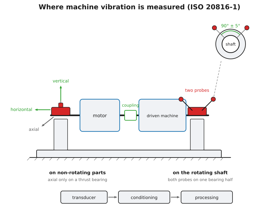
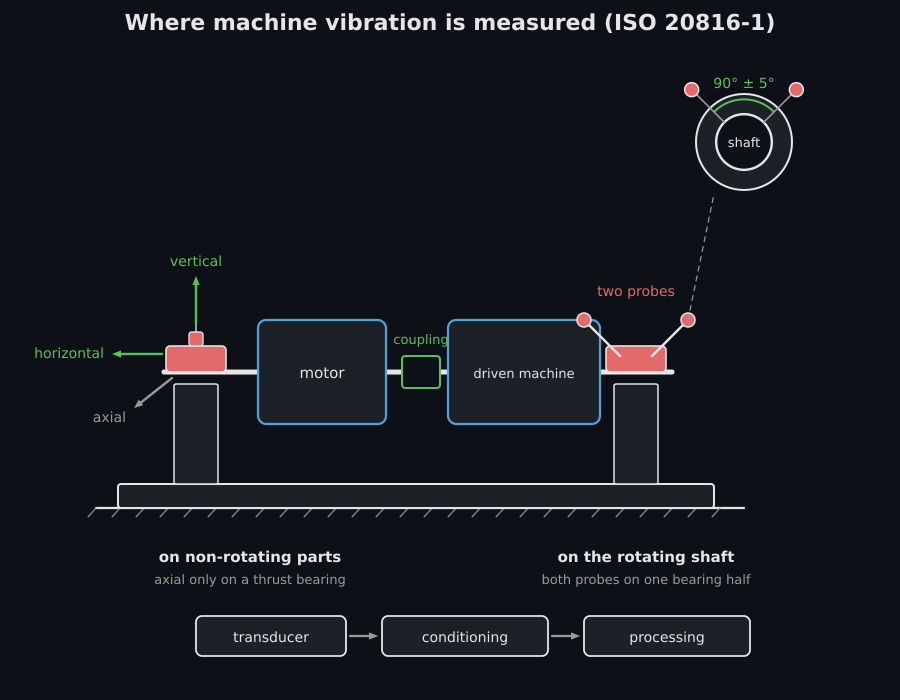
The two measurement families of Clause 4.4, on one train. The axial arrow is drawn as a foreshortened diagonal because it leaves the plane of an elevation.
The measured quantity is broad-band, and the vibration severity is the largest magnitude found at any bearing at rated speed under steady operation (4.3.3). It is that single number the zones grade.
2. Four zones, not a pass and a fail
Section titled “2. Four zones, not a pass and a fail”Clause 6.3.2.3 grades rather than judges:
| Zone | What it means |
|---|---|
| A | Where newly commissioned machines normally fall. |
| B | Acceptable for unrestricted long-term operation. |
| C | Unsatisfactory for long-term continuous operation; the machine may run a limited period until remedial action can be arranged. |
| D | Severe enough to cause damage. |
Three boundaries separate them, and evaluation_zone is the comparison
itself. It is deliberately blind to the quantity: the parts of the series set
boundaries on shaft displacement, housing velocity or housing acceleration, and
the grading is the same in all three. A magnitude exactly on a boundary is the
top of the zone below it, which is how the tables print their limits.
from phonometry import vibration
# Three boundaries from whichever part of ISO 20816 applies, in mm/s r.m.s.zones = vibration.ZoneBoundaries(2.8, 7.1, 11.2)print(vibration.evaluation_zone([0.9, 3.4, 8.0, 20.0], zones))   # ['A' 'B' 'C' 'D']print(vibration.evaluation_zone(2.8, zones))                     # A, the limit of A
The boundaries have to rise through the zones, and ZoneBoundaries refuses a
set that does not: out of order they would grade a good machine as a bad one
and say nothing.
3. The criterion is a curve, not a number
Section titled “3. The criterion is a curve, not a number”Velocity carries a severity criterion over a wide speed range, which is why the
tables are written in it. But a single velocity limit regardless of frequency
allows unacceptable displacement at low frequency and unacceptable acceleration
at high frequency (6.3.2.1). So the criterion of Figure 9 is flat only between
two corner frequencies, and slopes outside them. Annex C.2 writes it as
Formula (C.1), and allowable_velocity is that formula:
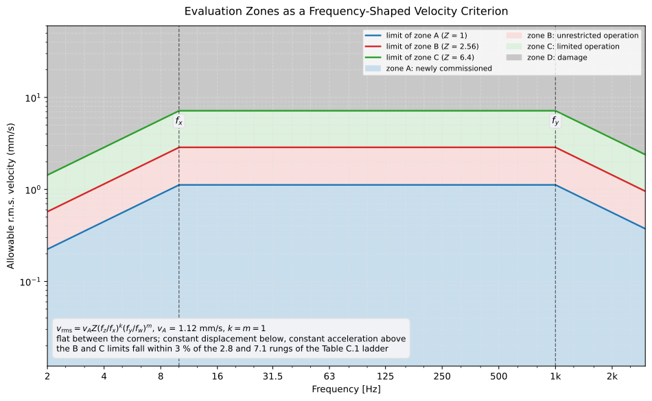
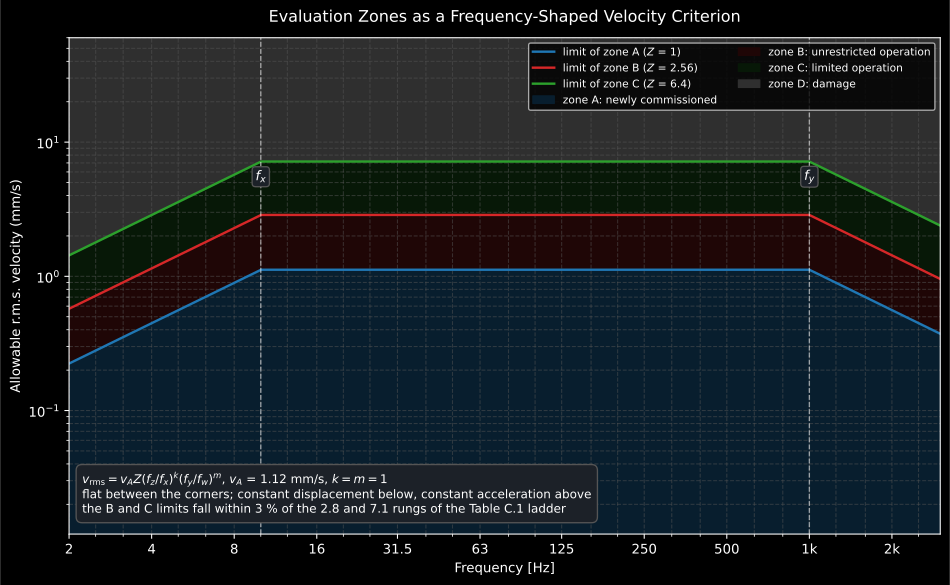
One curve, moved onto the three boundaries by the factor Zbound. Below the
lower corner the criterion holds displacement constant, above the upper one it
holds acceleration constant.
Show the code for this figure
import matplotlib.pyplot as pltimport numpy as npfrom phonometry import vibration
freq = np.logspace(np.log10(2.0), np.log10(3000.0), 600)common = dict(constant_velocity_mm_s=1.12, corner_low_hz=10.0,              corner_high_hz=1000.0)for zone, factor in vibration.ZONE_LIMIT_FACTORS.items():    plt.plot(freq, vibration.allowable_velocity(freq, zone_factor=factor,                                                **common),             label=f"limit of zone {zone}")plt.xscale("log"); plt.yscale("log"); plt.legend()plt.xlabel("Frequency [Hz]"); plt.ylabel("Allowable r.m.s. velocity (mm/s)")plt.show()
The factor Zbound moves the one curve onto the three limits, and Annex C.2
prints what it takes: 1 for the limit of zone A, 2.56 for zone B and
6.4 for zone C. Those are 1.6 squared and 1.6 to the fourth, near enough,
and the ladder of Table C.1 steps by about 1.6 as well, so the three limits
land close to its rungs without falling on them.
from phonometry import vibration
common = dict(constant_velocity_mm_s=1.12, corner_low_hz=10.0,              corner_high_hz=1000.0)for zone, factor in vibration.ZONE_LIMIT_FACTORS.items():    limit = vibration.allowable_velocity(100.0, zone_factor=factor, **common)    print(zone, round(float(limit), 2))       # A 1.12 / B 2.87 / C 7.17
The corner frequencies and the exponents belong to the machine, and the specific parts state them. The defaults of 1 are the physical reading of the shape rather than a value taken from anywhere: constant displacement below the lower corner, which makes the allowable velocity rise at 6 dB per octave, and constant acceleration above the upper one, which makes it fall at the same rate. The curve is lowest at both ends and flat in between.
4. A change is a vector
Section titled “4. A change is a vector”Criterion I judges a magnitude. Criterion II (6.3.3) judges a change from an established baseline, and it exists because a machine can go wrong inside zone B: a significant increase or decrease can occur, and require action, long before zone C is reached.
The trap is that a broad-band magnitude cannot express a change. Annex D makes the point with a machine whose vibration fell from 3 mm/s to 2.5 mm/s while its phase swung from 40° to 180°:
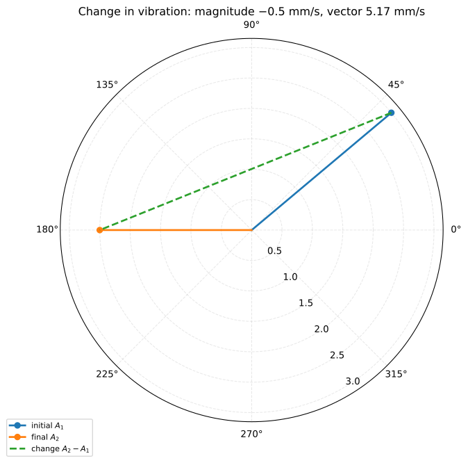
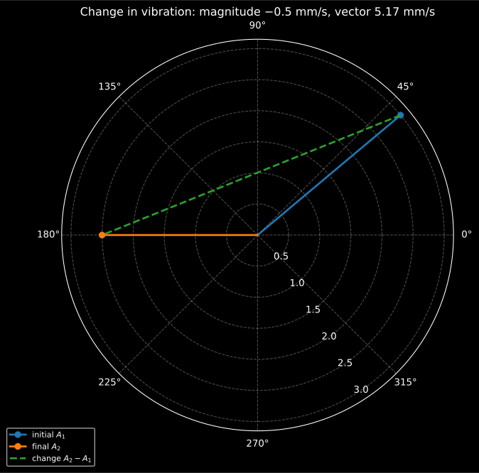
The magnitude fell by half a millimetre per second. The vibration moved by 5.2, ten times as much.
from phonometry import vibration
change = vibration.vibration_vector_change(3.0, 40.0, 2.5, 180.0)print(round(change.magnitude, 2))          # 5.17 mm/s: the real changeprint(round(change.magnitude_change, 2))   # -0.5 mm/s: what magnitudes say
This is why phase belongs in a trend record. A component that swings while its contribution falls changes the machine, and a magnitude-only criterion sees a small improvement.
5. Where the numbers come from
Section titled “5. Where the numbers come from”For a machine covered by a part of the series, from that part. For one that is not, and where no experience is available, Annex C.1 offers Table C.1: a ladder of preferred magnitudes and the range each boundary is typically drawn from, with small machines (electric motors up to 15 kW) at the low end and large ones on flexible supports at the high end.
from phonometry import vibration
print(vibration.TYPICAL_ZONE_BOUNDARY_RANGES_MM_S["B/C"])   # (1.8, 9.3)print(vibration.TYPICAL_BOUNDARY_LADDER_MM_S[:5])           # the first rungs
The ranges overlap on purpose: a large machine’s A/B boundary can sit above a small machine’s B/C one, which is what makes them ranges rather than limits. They are a starting point for agreement between supplier and customer, and the standard says plainly that the values assigned to zone boundaries are not themselves intended to serve as acceptance specifications (6.3.2.5).
6. The numbers, for the machines a plant is full of
Section titled “6. The numbers, for the machines a plant is full of”Part 1 fixes the shape of the judgement and declines to give boundaries. ISO 10816-3 gives them, for the machines an industrial site is actually made of: rotary compressors, generators, electric motors of any type, blowers and fans, steam turbines up to 50 MW and industrial gas turbines up to 3 MW, all measured in situ on the non-rotating parts.
Two questions place a machine in one of four classes.
How big it is (4.2). Group 1 is a large machine with rated power above 300 kW, or an electrical machine of shaft height 315 mm or more; the upper bound of 50 MW is printed in the title of Table A.1 rather than in the clause. Group 2 is a medium-sized machine above 15 kW and up to and including 300 kW, or an electrical machine of shaft height from 160 mm up to but not including 315 mm.
What it stands on (4.3). If the lowest natural frequency of the combined machine and support system, in the direction being measured, is at least 25 % above the main excitation frequency, which is usually the running speed, the support is rigid in that direction. Every other support is flexible. The clause is explicit that the two can differ within one machine: a foundation stiff vertically and soft horizontally is judged by the rigid table in one direction and the flexible table in the other.
Each of the four classes is then stated twice, once in displacement and once in velocity, and 5.2.3 settles the disagreement: the more restrictive severity zone applies.
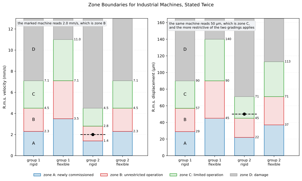
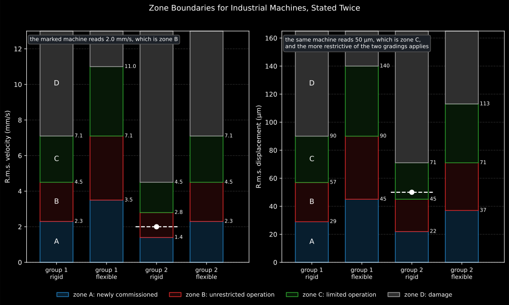
The same machine, read two ways. Velocity says zone B; displacement says zone C; the grade is C.
from phonometry import vibration
print(vibration.industrial_machine_zone("group_2", "rigid", velocity_mm_s=2.0))# Bprint(vibration.industrial_machine_zone("group_2", "rigid", displacement_um=50.0))# Cprint(    vibration.industrial_machine_zone(        "group_2", "rigid", displacement_um=50.0, velocity_mm_s=2.0    ))  # C
A month of daily readings is one call. Pass the run as an array and each reading is graded on its own, which is the series Criterion II is judged on: that criterion does not read the zone at all, it reads the change from the established baseline, and a machine can be well inside zone B and still owe an investigation.
import numpy as np
from phonometry import vibration
trend = np.array([1.0, 2.0, 3.5, 5.0])print(vibration.industrial_machine_zone("group_2", "rigid", velocity_mm_s=trend))# ['A' 'B' 'C' 'D']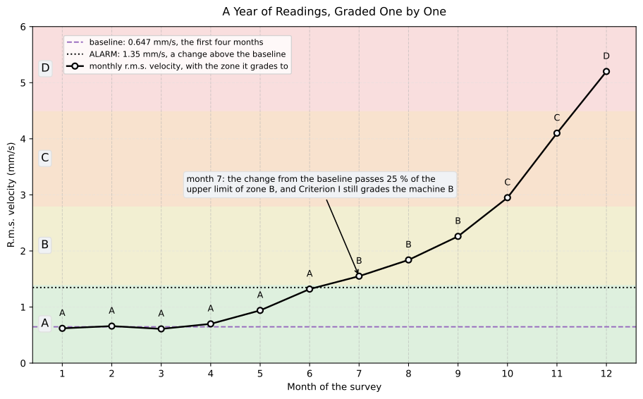
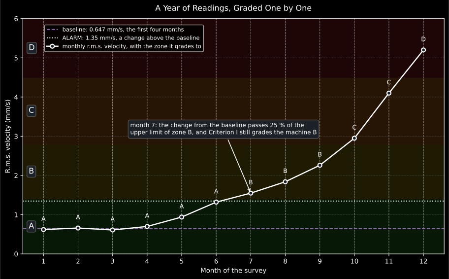
Criterion II sees it first. The machine is still graded B in month 7, and the change from its own baseline has already passed what 5.3 asks to be investigated.
Give whichever quantities were measured. Annex A says velocity alone is enough in most cases, and that a machine whose spectrum is expected to carry low-frequency components should be judged on both. The limits are broad-band r.m.s. values between 10 Hz and 1 kHz, or from 2 Hz for a machine running below 600 r/min.
The edition implemented here is ISO 10816-3:2009, which ISO 20816-3:2022 has since replaced. Part 3 is the one part of the series not held here, so the boundaries come from its direct predecessor, and this page says so rather than implying a currency it does not have.
7. ALARM and TRIP, with numbers behind them
Section titled “7. ALARM and TRIP, with numbers behind them”Part 1 describes the two operational limits and leaves their values to the parts. Part 3 gives them, and the two are set from different things.
A significant change (5.3) is an increase or a decrease of more than 25 % of the upper limit of zone B, measured at the same transducer location and orientation and under the same operating conditions. That is Criterion II made arithmetic.
An ALARM (5.4.1) sits 25 % of the upper limit of zone B above the established baseline for that position, and should not normally exceed 1.25 times that limit. Both halves matter. Set from the baseline, an alarm on a quiet machine can fall well inside zone B, which is the point of it. Capped at 1.25 times the limit, an alarm on a machine whose baseline has crept up cannot follow it indefinitely.
A TRIP (5.4.2) relates to the mechanical integrity of the machine, so it is generally the same for every machine of a design and is not tied to the baseline. It will normally lie within zone C or D, and should not exceed 1.25 times the upper limit of zone C.
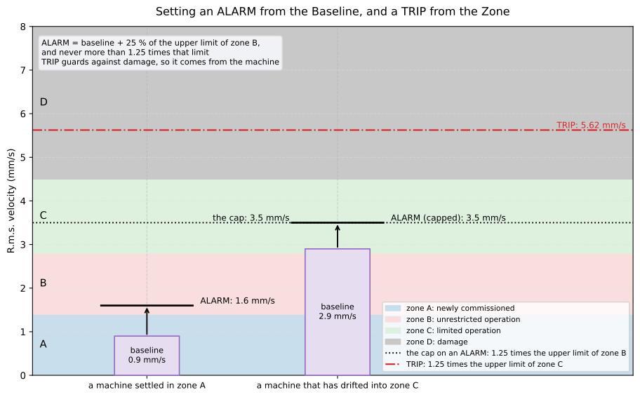
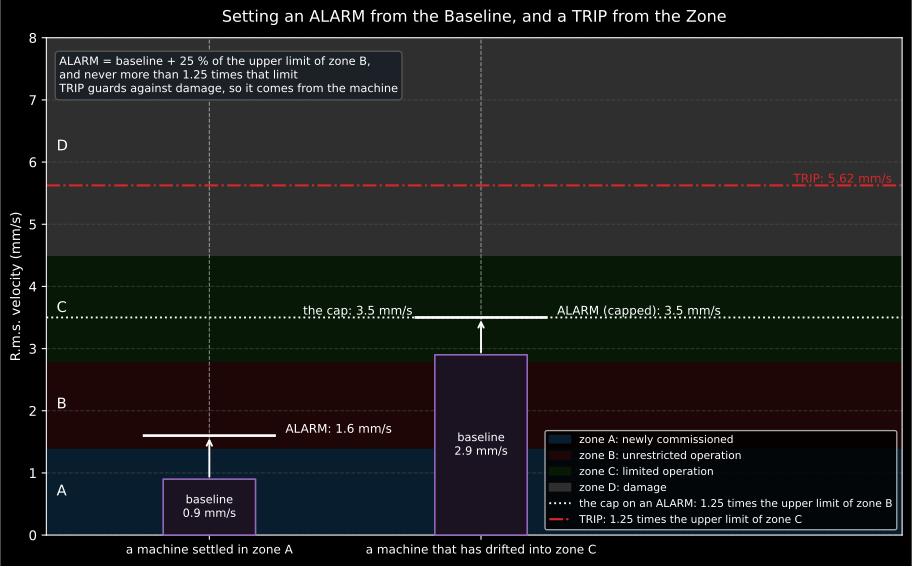
The quiet machine gets an alarm inside zone B. The one that has drifted runs into the cap.
from phonometry import vibration
limits = vibration.INDUSTRIAL_MACHINE_ZONES["group_2", "rigid"].velocity_mm_s
print(vibration.is_significant_change(0.8, limits.b_c))   # Trueprint(vibration.is_significant_change(0.6, limits.b_c))   # Falseprint(round(vibration.alarm_limit(0.9, limits.b_c), 3))   # 1.6print(round(vibration.alarm_limit(2.9, limits.b_c), 3))   # 3.5, at the capprint(round(vibration.trip_limit(limits.c_d), 3))         # 5.625
8. Gear units, and a rating instead of a machine class
Section titled “8. Gear units, and a rating instead of a machine class”Part 3 asks what the machine is and what it stands on. Part 9 asks a different question: it grades a gear unit against a rating number, chosen for the unit at the start of negotiation, and the rating indexes a row of boundaries.
There are three ratings, one per quantity: DR for shaft relative
peak-to-peak displacement, VR for housing r.m.s. velocity and AR for
housing true peak acceleration. Table 1 fixes the unit each is stated in,
micrometres, millimetres per second and metres per second squared; the three
names are spelled out under Table 5 and defined in Annex A. Tables 2, 3 and 4
give the boundaries.
Those three tables are one ladder seen three times. Every printed row is three consecutive rungs of 2, 3.15, 5, 8, 12.5, 20, 31.5, 50, 80, 125, 200, 315, with the rating itself as the B/C boundary and its neighbours as the other two. So choosing a rating is choosing a rung, and the library refuses a rating between two rows rather than interpolating one: the ladder is an agreement, not a continuum.
Table 5 is where a unit gets its ratings. Class I is special-purpose precision parallel-shaft units, class II general-purpose parallel-shaft, helical and spiral-bevel units, class III epicyclic units, and class IV straight-cut units; subclass a) covers any power and subclass b) splits by it.
from phonometry import vibration
ratings = vibration.GEAR_UNIT_CLASSES["III", "a"]print(ratings.displacement, ratings.velocity, ratings.acceleration)# 80.0 8.0 125.0
boundaries = vibration.gear_unit_zone_boundaries("velocity", ratings.velocity)print(boundaries.as_tuple)                          # (5.0, 8.0, 12.5)print(vibration.evaluation_zone(6.0, boundaries))   # B
Only the subclass a) rows carry an acceleration rating. Every b) row prints
“no information available at this time”, and the library carries that as
None rather than filling the gap with a plausible number.
The rating curves, and where Part 1 reappears
Section titled “The rating curves, and where Part 1 reappears”A rating is not only a set of three boundaries: Annex A draws it as a curve against frequency, so a filtered measurement can be judged line by line rather than as one broad-band value. The rating of a shaft or a position is then the lowest curve that encloses its whole spectrum.
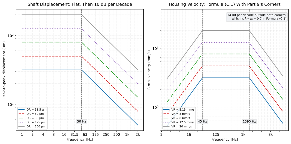
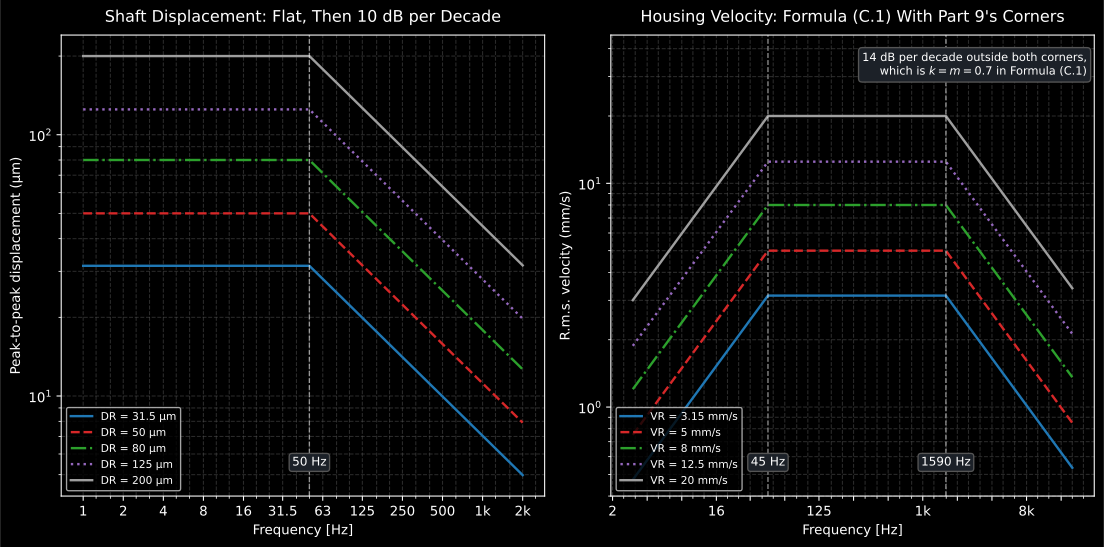
Left, Figure A.1; right, Figure A.2. The right-hand family is the criterion of section 3 again, with the corners and the slope Part 9 states.
from phonometry import vibration
print(round(float(vibration.gear_housing_velocity_limit(3000.0, rating=8.0)), 2))# 5.13 mm/s: a 3 kHz mesh line is judged against less than the ratingprint(round(float(vibration.gear_shaft_displacement_limit(500.0, rating=80.0)), 1))# 25.3 µm
The velocity curve is worth a second look. Flat between two corners and falling
outside them at one rate is exactly Formula (C.1) of Part 1, and this is that
formula with = 45 Hz, = 1590 Hz and , which is 14 dB
per decade. The library computes it by calling allowable_velocity, so the two
parts of the series share one curve rather than two implementations of it.
What Part 9 does not repeat
Section titled “What Part 9 does not repeat”ALARM and TRIP: 8.2 sends the reader to Part 1 for them, which is section 7 of this page. Acceptance criteria: 8.3 says they are agreed between manufacturer and customer, are historically specified inside zone A or B, and would normally not exceed 1.25 times the A/B boundary, which for a class II unit judged on velocity is 3.94 mm/s.
Measurement is Clause 6. Shaft displacement is read relative to the housing by non-contacting probes in orthogonal pairs through the journal bearing housing, and the combined mechanical and electrical runout should not exceed a quarter of the allowable displacement at shaft rotational frequency, or 6 µm, whichever is greater. Housing vibration is read on a rigid section such as a bearing block, in up to three orthogonal directions, two of them perpendicular to the gear axis; a housing panel that supports no bearing does not give a true indication of the unit.
Covered
The four evaluation zones and the grading of 6.3.2.3, the frequency-shaped criterion of Figure 9 as Formula (C.1) with the zone factors of Annex C.2, the typical ranges and ladder of Table C.1, and the vector reading of a change from Annex D, through
ZoneBoundaries,evaluation_zone,allowable_velocityandvibration_vector_change. For industrial machines, the boundaries of Tables A.1 and A.2 in both quantities, the most-restrictive rule of 5.2.3, the significant change of 5.3 and the ALARM and TRIP settings of 5.4, throughINDUSTRIAL_MACHINE_ZONES,industrial_machine_zone,is_significant_change,alarm_limitandtrip_limit. For gear units, the three rating tables and the classification of ISO 20816-9, and the two rating curves of its Annex A, throughGEAR_UNIT_ZONES,GEAR_UNIT_CLASSES,gear_unit_zone_boundaries,gear_shaft_displacement_limitandgear_housing_velocity_limit.Not covered
The zone boundaries of the machine-specific parts this page does not name, which it takes as inputs; the shaft criterion of Figure 10, whose values Annex C.1 declines to give for machines no part covers, on the grounds that such machines are not normally fitted with shaft transducers; and the current third edition of Part 3, ISO 20816-3:2022, which is not held here, so its predecessor supplies the industrial boundaries.
References
Section titled “References”- International Organization for Standardization. (2009). Mechanical vibration — Evaluation of machine vibration by measurements on non-rotating parts — Part 3: Industrial machines with nominal power above 15 kW and nominal speeds between 120 r/min and 15 000 r/min when measured in situ (ISO 10816-3:2009). The machine groups of 4.2 and the support classification of 4.3, the zone boundaries of Tables A.1 and A.2 in both quantities with the measurement band Annex A states, the most-restrictive rule of 5.2.3, the significant change of 5.3 and the ALARM and TRIP settings of 5.4. This edition has been superseded by ISO 20816-3:2022, which is not held here; the boundaries are taken from the edition that is.
- International Organization for Standardization. (2016). Mechanical vibration — Measurement and evaluation of machine vibration — Part 1: General guidelines (ISO 20816-1:2016). The measurement positions of 4.4, the vibration severity of 4.3.3, the four evaluation zones of 6.3.2.3, Criterion II of 6.3.3, the velocity criterion of Figure 9 as Formula (C.1) with the zone factors of Annex C.2, the typical boundary ranges of Table C.1 and the vector change of Annex D. This first edition cancelled and replaced ISO 7919-1:1996 and ISO 10816-1:1995.
- International Organization for Standardization. (2020). Mechanical vibration — Measurement and evaluation of machine vibration — Part 9: Gear units (ISO 20816-9:2020). The rating system: the units of Table 1, the shaft and housing measurements of Clause 6, the evaluation zones of 8.2, the acceptance ceiling of 8.3, the boundary tables 2, 3 and 4, the classification of Table 5, and the rating curves of Annex A.